- 易迪拓培训,专注于微波、射频、天线设计工程师的培养
HFSS15: ANSYS EM CAD Integration through Workbench
录入:edatop.com 点击:
ANSYS Electromagnetics CAD integration is a Workbench feature available for ANSYS Electromagnetics 3D Products - HFSS, Maxwell and Q3D, as the ANSYS Framework. The feature is available only through Workbench, not available with standalone ANSYS Electromagnetics products.
ANSYS CAD integration provides a bi-directional dynamic link through Workbench, which makes it possible to get updated geometry from CAD and to modify CAD parameters in ANSYS Electromagnetics products to return updated geometry. The feature is non-associative due to a need to reassign boundaries if modified CAD model is to be used. The process creates a User Defined Model (UDM) for each geometry source
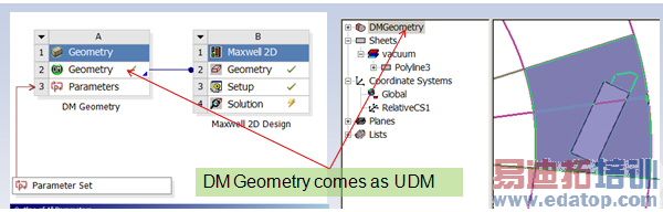
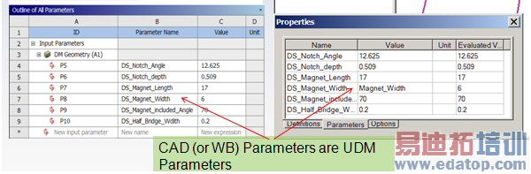
The User Defined Model (UDM) format makes it possible to exchange parameters.
See here for further description of the UDM feature and function.
ANSYS Electromagnetics CAD integration makes it possible to consume geometry from multiple upstream source which can be any CAD or ANSYS Electromagnetics product. This feature supports direct interfaces with all major CAD systems.
• Pro/E Wildfire
• UG NX
• CATIA V5
• SolidWorks
• ANSYS Design Modeler (DM)
• ANSYS SpaceClaim Direct Modeler (SCDM)
CAD software must be installed on user machine
• Not required on solve nodes
Platforms Supported
• Windows 32 bit
• Windows 64 bit
• Linux is NOT supported but it is possible setup project on windows and use Linux nodes for solves.
See the following sections:
CAD Integration Functionality
CAD Integration and Geometry Sharing
Bi-Directional CAD Integration
CAD Integration Model Edits
Multiple Geometry Links for CAD Integration
CAD Integration Functionality
Healing with CAD Integration
Important Geometry Options for CAD Integration
HFSS 学习培训课程套装,专家讲解,视频教学,帮助您全面系统地学习掌握HFSS
上一篇:Antennas on Mast
下一篇:Apache Software

