- 易迪拓培训,专注于微波、射频、天线设计工程师的培养
HFSS15: Assigning Lumped Ports
录入:edatop.com 点击:
Lumped ports are similar to traditional wave ports, but can be located internally and have a complex user-defined impedance. Lumped ports compute S-parameters directly at the port. An example use is modeling microstrip structures.
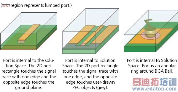
A lumped port can be defined as a rectangle from the edge of the trace to the ground or as a wave port. The default boundary is perfect H on all edges that do not come in contact with the metal or with another boundary condition.
Their setup varies slightly depending on whether the solution is modal or terminal.
Note | Use wave ports to model exterior surfaces through which a signal enters or exits the geometry. |
The following restrictions apply:
• The complex full port impedance must be non-zero and the resistance must be non-negative.
• Only one port mode is allowed, or one terminal if it is a terminal solution.
• An integration line must be defined for driven ports.
• Each terminal that is identified by an edge selection must have each edge contained by some non port face. If this condition is not satisfied, an error message is issued. If you see the error message, you should abort the solve and correct the geometry.
HFSS-IE Lumped Ports
The lumped ports in HFSS-IE ports are different than those in HFSS. The HFSS-IE lumped ports impress a one volt difference between the terminal and its reference while an HFSS lumped port impresses an electric field between the terminal and its reference.
To ensure a valid port, the maximum distance from the terminal to the reference should be less than a twentieth of a wavelength. If this condition is violated, a warning occurs.
For HFSS-IE:
• For auto assignment to work you must enable Auto-assign terminals on ports on the HFSS-IE Options: General Options Tab.
Otherwise, for either HFSS or HFSS-IE:
• Manually assign a terminal. Select any connected edge(s) and/or face(s) of conductors that touch the port.
• Select Excitations>Auto Assign Terminals.
This will bring up a dialog box for you to select the objects used for “reference conductors.”
HFSS 学习培训课程套装,专家讲解,视频教学,帮助您全面系统地学习掌握HFSS
上一篇:Assigning Perfect E Boundaries
下一篇:Assigning Frequency Dependent Material: Multipole Debye Model Input

